CM YO4MM-Srunken quad type antenna modeled by YO5OUC
CE
SY lambda=20 'wavelength
SY rad=0.001 'wire radius
SY seg=40 'nr. of segments per quarter wavelength
SY d=0.1 'the space distance between lines
SY d1=0.1
SY l=0.185*lambda 'quarter wave length
SY h=7
SY alf=130
GW 1 seg -(lambda/8)*cos(45) 0 d/2+h 0 0 (lambda/8)*sin(45)+d/2+h rad
GW 2 seg 0 0 (lambda/8)*sin(45)+d/2+h (lambda/8)*cos(45) 0 d/2+h rad
GW 3 seg -(lambda/8)*cos(45) 0 -d/2+h -d1/2 0 -(lambda/8)*sin(45)-d/2+h rad
GW 4 seg d1/2 0 -(lambda/8)*sin(45)-d/2+h (lambda/8)*cos(45) 0 -d/2+h rad
GW 5 seg -(lambda/8)*cos(45) 0 d/2+h -(lambda/8)*cos(45)-l*cos(alf) l*sin(alf) d/2+h rad
GW 6 seg -(lambda/8)*cos(45) 0 -d/2+h -(lambda/8)*cos(45)-l*cos(alf) l*sin(alf) -d/2+h rad
GW 7 1 -(lambda/8)*cos(45)-l*cos(alf) l*sin(alf) d/2+h -(lambda/8)*cos(45)-l*cos(alf) l*sin(alf) -d/2+h rad
GW 8 seg (lambda/8)*cos(45) 0 d/2+h (lambda/8)*cos(45)+l*cos(alf) -l*sin(alf) d/2+h rad
GW 9 seg (lambda/8)*cos(45) 0 -d/2+h (lambda/8)*cos(45)+l*cos(alf) -l*sin(alf) -d/2+h rad
GW 10 1 (lambda/8)*cos(45)+l*cos(alf) -l*sin(alf) d/2+h (lambda/8)*cos(45)+l*cos(alf) -l*sin(alf) -d/2+h rad
GW 11 1 -d1/2 0 -(lambda/8)*sin(45)-d/2+h d1/2 0 -(lambda/8)*sin(45)-d/2+h rad
GE 1
GN 2 0 0 0 3 0.0001
EK
EX 0 11 1 0 1 0 0
FR 0 0 0 0 14.1 0
EN
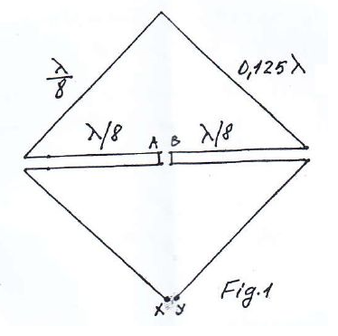
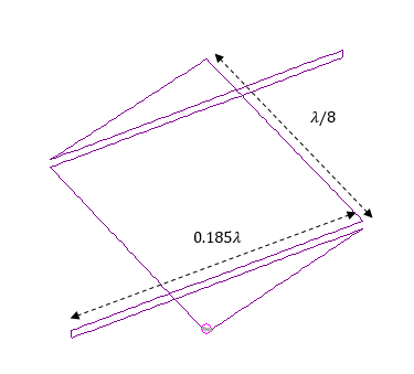
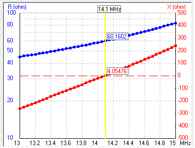
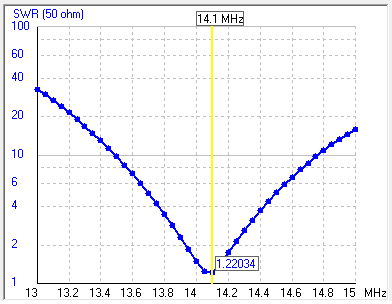
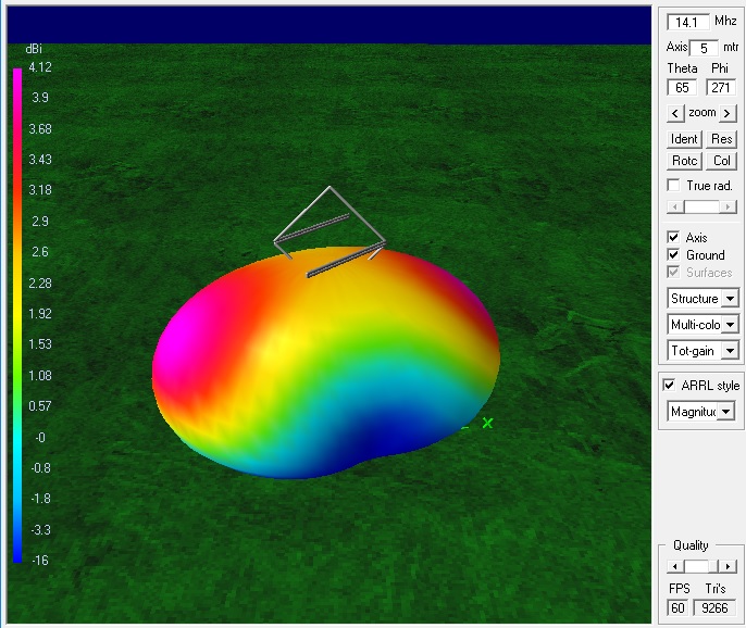
This is a very nice antenna for 20 meters band suitable vor very narrow backyards. YO4MM/Mac is using this antenna from 2013. The first description was made by Mr. Lesovici in radioamator.ro where its schematic was ploted. An ordinary quad antenna was shrunken from lambda/4 to lambda/8 at each side. Using the parametric model in 4NEC2 I was happy to plot the results of this design and to show how easy one can tunne it in any band by adjusting the value of lambda parameter in the source code. The two srunken sides can be slope down under an angle alfa and used for ancoring the sistem. The effect of the alfa parameter when it goes horizontaly is to change the main beam direction as then one rotate the quad. The antenna hight is 7 meters over a real ground. Mr. Lesovici imagined a square quad with its srunken arm inside the square. This is posible when one uses a low velocity transmition coax line with a velocity factor between 0.5-0.75. Then the length is shortened at velocity factor*0.185lambda. The length of the srunken shorted lines will adjust the input impedance from 60 to 100 Ohms.